
Biogas Plant Design
Thanks for such information Felix ter Heegde (http://www.ppre.uni-oldenburg.de/download/Biogas/Biogas2011/03_20110427_Biogas_plant_sizes_and_dimensions.docx)
Biogas Plant Design (Chapter 3)
2 Plant design
2 Plant design
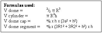 |
| biogas plant formula |
A simple plant design similar to the designs in Vietnam (KT), Cambodia (modified Dheenbandu) or Tanzania (modified Camartec) is used for this example.
 |
| Plant Layout |
In this hemi-spherical design, the digester volume is the volume under the lower slurry level(LSL), and the gas storage volume is the volume between the lower and higher slurry level (HSL).
For all plants with internal gas storage, the gas storage volume in the plant is equal to the volume of the compensation volume
2.1 Total plant volume
 |
| Dome Radius |
 |
| digester volume dimensions |
As pic 1 shows, part of the dome volume, over the higher slurry level, is not used by a well functioning installation. The volume, often referred to as “dead volume” is required, however, to accommodate the floating layer on top of the slurry. In addition, when gas production is less then nominal (cold seasons) or when gas is slowly leaking, the higher slurry level can rise (up to overflow level). For that reason, the total plant volume used for dimensioning should be higher than the plant size range volume results. For this example, 20% addition is allowed for this dead volume. Hence, taking plant size 1 for the example, the total plant volume (digester + gas storage + dead volume) arrives at 3.90 x 1.2 = 4.68 m3.
2.2 Dome radius
The dome radius, R dome, follows from: R dome = (V tot / 2/3 π)1/3. For plant size 1, then:
R dome1 = (4.68 / 2/3 π)1/3 = 1.3 [m]
2.2 Calculating digester volume dimensions
This calculation serves to find the upper level of the digester volume, or the height of the lower slurry level (LSL) in the dome. For this, the digester volume (calculated at 3.00 m3 in 1.2.1 iii) can be seen as the total dome volume minus the volume of the “dome cap”. In this way V dig cap1 = V dome1 – V dig1.
Or: V dig cap1 = 4.68 – 3.00 = 1.68 [m3]
To apply the formula V dome cap equals π/6 x h x (3a2 + h2), the dome (R dome = 1.3 [m]) has to be draw precisely on scale. Through “trial and error”, then, you should find when h = 0.7 [m] a will be 1.66 [m],
and V dome cap1 = π/6 x 0.7 x (3 x 1.662 + 0.72) = 1.66 [m3] .
The digester volume, then, results in V dig1 = Vdome1 – Vdome cap1
Vdig1 = 4.68 – 1.66 = 3,02 [m3] which is close to the design volume of 3.00 [m3]. The LSL equals Rdome1 minus a1; LSL1 = 1.30 – 0.70 = 0.60 [m]
 |
| gas storage volume dimensions |
2.3 Calculating gas storage volume dimensions
The gas storage volume should be at least 0.90 [m3] (see 1.2.1 vii).
The volume of a segment of a sphere is:
V segment = π/6 x (3R12 + 3R22 + h2) x h
R1 is equal to a(from 2.3); R1 thus equals to 1.66 [m].
To find R2 you’ll have to use the drawing again, and measure h and R2 . You’ll find that when h = 0.25 [m] then R2 = 0,97 [m] and
Vseg1 = π/6 x (3 x 1.162 + 3 x 0.972 x 0.252) x 0.25 = 0.91 [m3].
2.4 Plant dimensions
From the above follows for plant size 1 that:
R dome = 0.130 [m]
LSL = 0.130 – 0.70 = 0.60 [m]
HSL = 0.60 + 0.25 = 0.85 cm
Whereby:
The LSL is also the height of the manhole entry in the plant (beam height or, for Vietnam, outlet pipe height)
The HSL is also to floor level height of the compensation chamber.
2.4 Overflow height.
The height of the overflow determines:
- the maximum pressure in the plant;
- the extent to which slurry can reach into the gas dome pipe, and;
- of course, the height determines the dimensions of the compensation chamber.
For the positioning of the overflow, there are two schools of thought:
1 The overflow should be positioned under the bottom of the dome pipe. This will avoid slurry reaching the bottom of the gas dome pipe. Slurry can reach the bottom of the dome pipe when plants are leaking gas or when, for temperature reasons or other, the gas production is significantly lower than the gas consumption over a prolonged period of time.
2 The overflow should be positioned higher than the bottom of the dome pipe. This allows a higher maximum pressure in the plant and makes the compensation chamber dimensions more economic. Slurry entering the dome pipe, then, is an indication of a mistake in the construction of the operation of the installation, and should be remedied.
In this example the overflow is placed 5 cm under the top of the dome.
 |
| overflow and pressure height |
2.5 Pressure height check
The pressure height is the maximum pressure that the installation can produce. This maximum pressure is limited by the LSL; when pressure increases to the point whereby the LSL is pushed down further below the beam / outletpipe level, biogas will escape through the compensation chamber.
As shown in the picture, the pressure height (ph) is the difference between overflow height (oh) and LSL.
 |
| Compensation chamber dimensions |
ph1 = 1.25 - 0.60 = 0.65 [m].
2.6 Compensation chamber dimensions
The volume of the compensation chamber (V cc) shall be equal to the plant’s gas storage volume. In case of “size 1”, then, V cc shall be 0.9 [m3]. Following the earlier position that the overflow level should be lower that the top of the dome, the compensation chamber height (cch) is the difference between the overflow height (oh) and the higher slurry level (HSL) (= compensation chamber floor level).
For the example size 1, the compensation chamber height then is 1.25 – 0.85 = 0.40 [m].
Assuming a cylindrical compensation chamber, the radius of the compensation chamber (R cc) follows from:
R cc = (V cc / (π x cch))1/2.
Or: R cc1 = (0.90 / (π x 0.40))1/2 = 0.84 [m]
2.7 Inlet floor and inlet pipe
To avoid reflux, the inlet floor height (ifh) should be higher than the overflow height (oh). For the example for plant size 1, ifh is 0.15 [m] higher than oh.
To avoid biogas escaping through the inlet pipe (toilet connection!), the top of the inlet entering the dome should be below the LSL. At the same time the inlet pipe height (iph) should not be too close to digester floor to prevent obstruction by debri. Typically, the iph should be about 0.30 [m] above the digester floor.
Finally, the inlet / pipe layout should allow entering a long stick in case of inlet pipe blockage.
 |
| Inlet floor and inlet pipe |
Domestic biogas plants Sizes and dimensions ( Chapter 1
Plant size range calculations (Chapter 2)
Biogas Plant Design (Chapter 3)
Thanks for such information Felix ter Heegde (http://www.ppre.uni-oldenburg.de/download/Biogas/Biogas2011/03_20110427_Biogas_plant_sizes_and_dimensions.docx)


0 comments:
Post a Comment